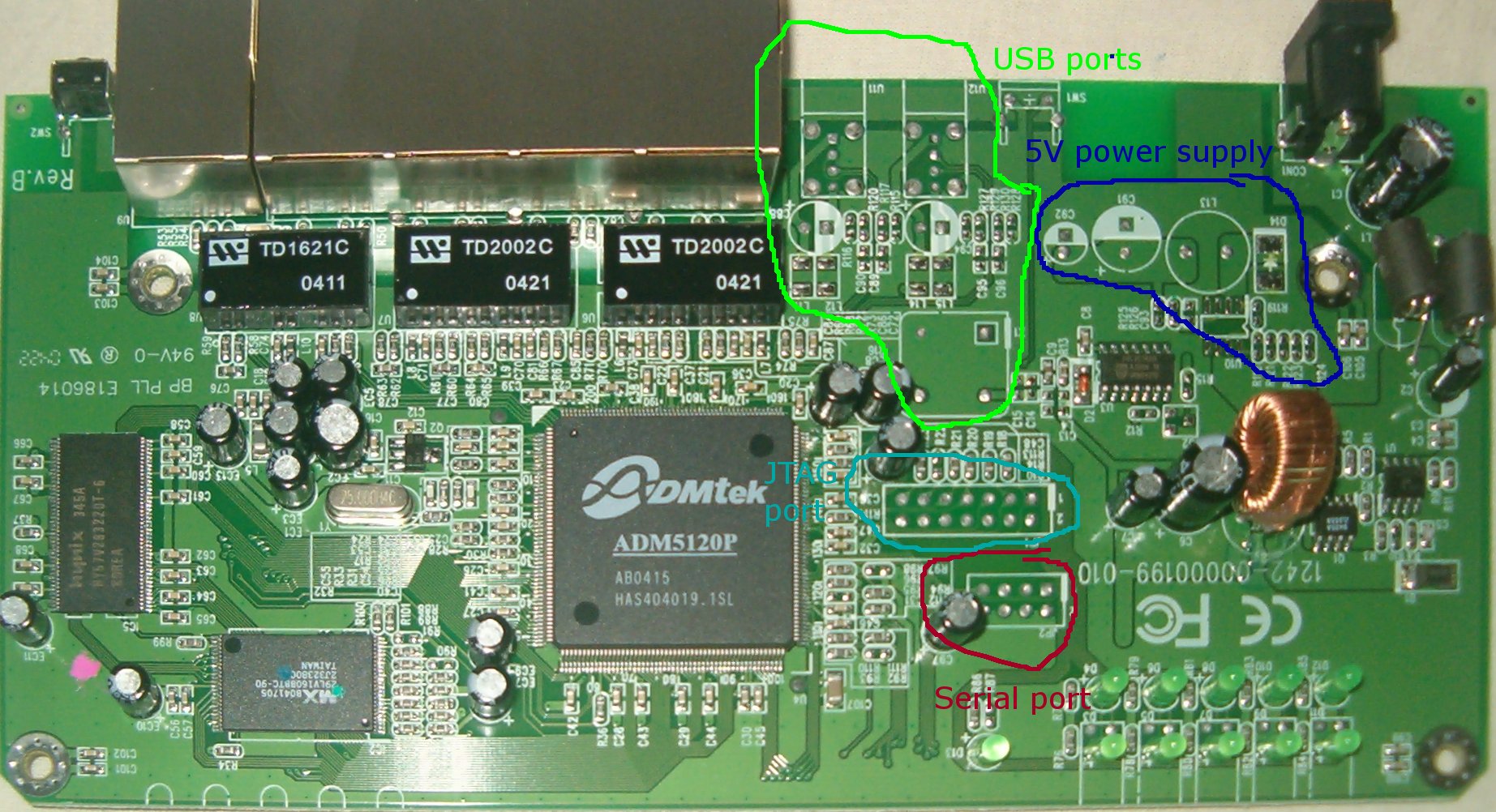
As you can see, the LB000021 has some unpopulated regions on the PCB. We'll be repopulating the 5V power supply and the USB-ports part.
Warning: The stock LB000021 firmware doesn't support USB. To use the USB-port, you should flash your router with firmware that supports it, e.g. this firmware.
The Sweex LB000021 is about the cheapest hardware router one can get. I bought mine for E25,- new. The fun thing about these routers is that there's a complete MIPS-architecture processor in it, the ADM5120, which runs Linux. One of the features of the ADM5120 is that it has an onboard USB-hostcontroller. In the LB000021, however, this feature is not used. In this tutorial I'll show you how to change that.
Disclaimer & warning
This is a hack, which works for me. However, I can't guarantee anything beyond
that. If it works for you too, good for you. If it doesn't and any bad stuff
happens, I'm not responsible. Secondly, you'll void your warranty by applying
this hack to your router.
Parts
For this hack, you'll need:
If you want the PCB to look pretty afterwards, you can use SMD resistors. I think
those'd be easier to solder too. I used normal 1/4W resistors, and they'll work too,
The interior of the LB000021
As you can see, the LB000021 has some unpopulated regions on the PCB. We'll be
repopulating the 5V power supply and the USB-ports part.
5V power supply
As you can see, the original 5V power supply consists of quite a lot of parts.
We'll take the dirty hack route here and replace them all with a simple 7805
and a capacitor.
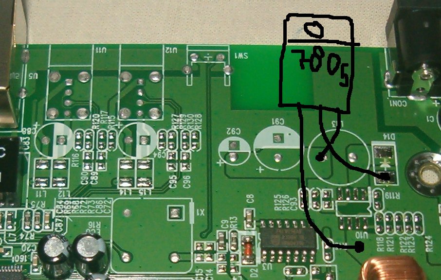
Connect the 7805 to the PCB as seen in the image. The green stuff isn't directly
solderable, you'll have to scrape it off with a knife till you see the copper PCB.
Use an 100uF capacitor to populate C91. Watch out for the polarity of the thing.
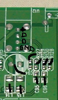
USB port
I'll explain how to populate the USB port the farthest away from the Ethernet ports.
If you want to repopulate the other port too, the process is similar.
| ID | Part | Remarks |
| U12 | USB connector | |
| R127 | Resistor 15K | |
| R128 | Resistor 15K | |
| R129 | Resistor 22 ohm | |
| R130 | Resistor 22 ohm | |
| C94 | Capacitor 100uF | |
| L14 | - | Shortcut the 2 pads |
| L15 | - | Shortcut the 2 pads |
| C95 | - | Leave open |
| C96 | - | Leave open |
48MHz oscillator
The processor'll need a 48MHz clocksignal to time the communication tot the USB-port.
Connect it like this:
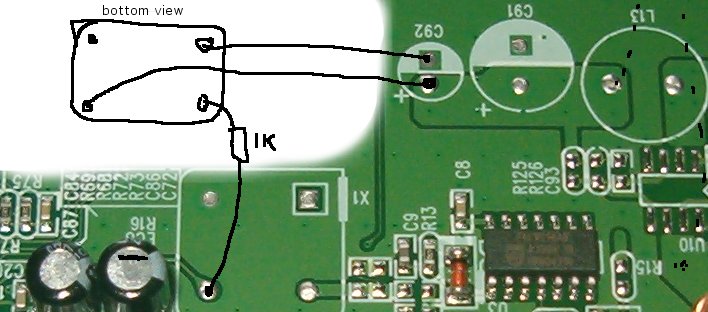
Be sure to short-circuit the 2 pads of R16 (unfortunately obscured by the 2 C's on
the photo). Alternatively, put the 1K resistor there.
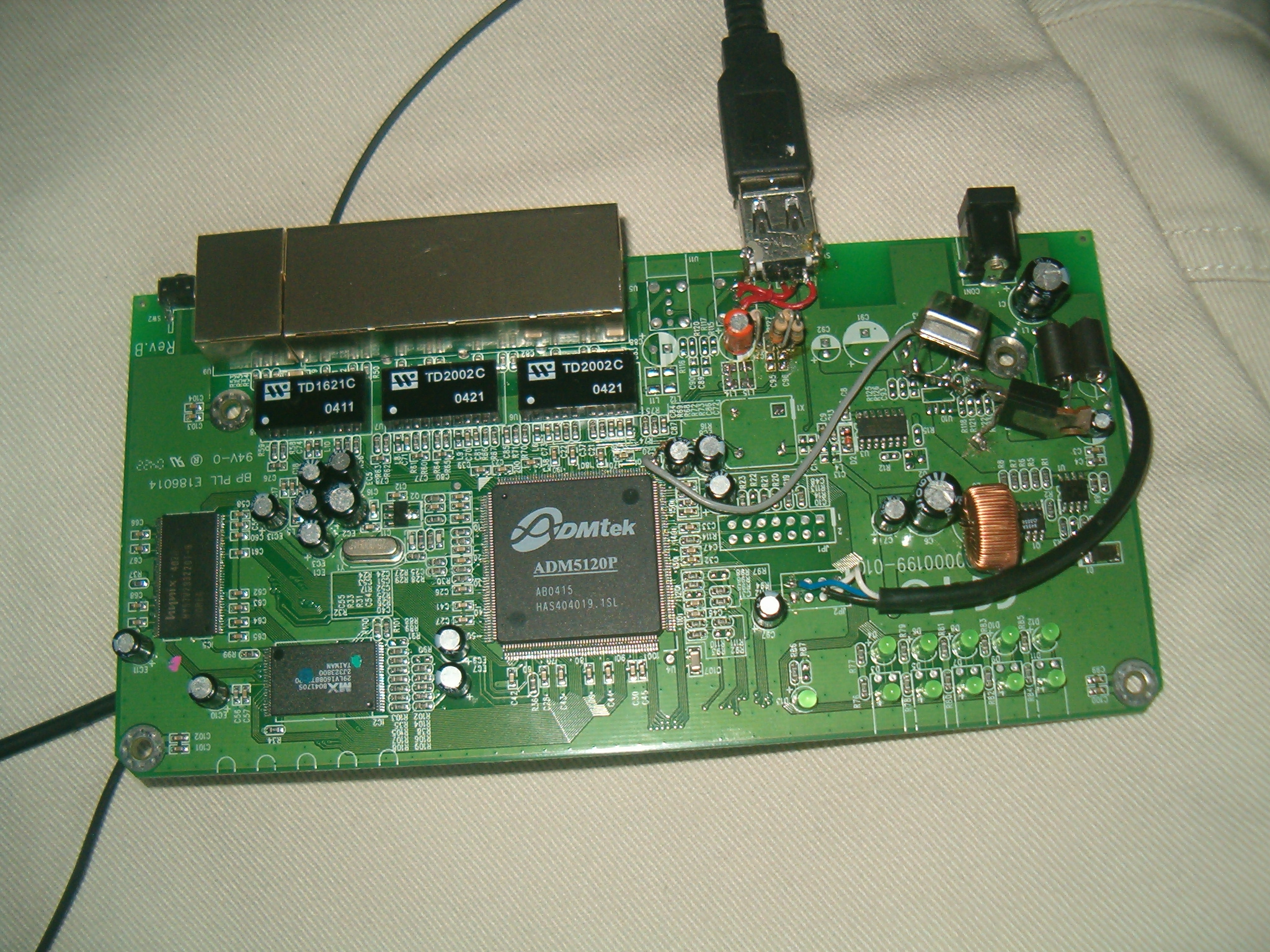
Hardware: Finished!
Your board now might look like this:
Testing your rig
A few things you might want to check before you plug an USB device into the rig.
Plug in your board and check:
If those points check out ok, you can go ahead and flash an USB-aware firmware
image in the router.